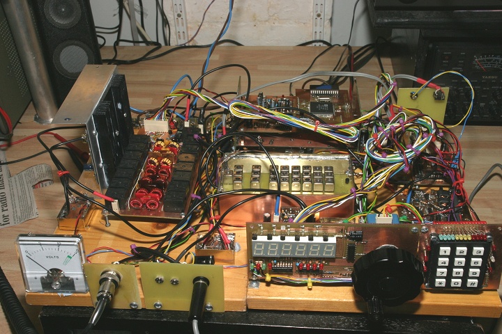
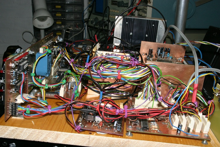
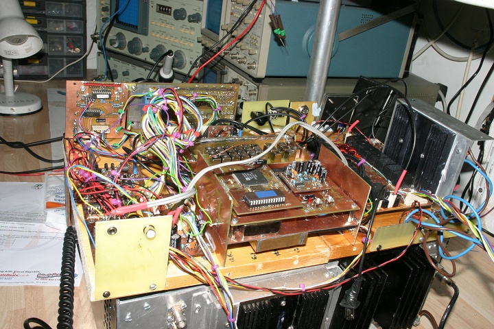
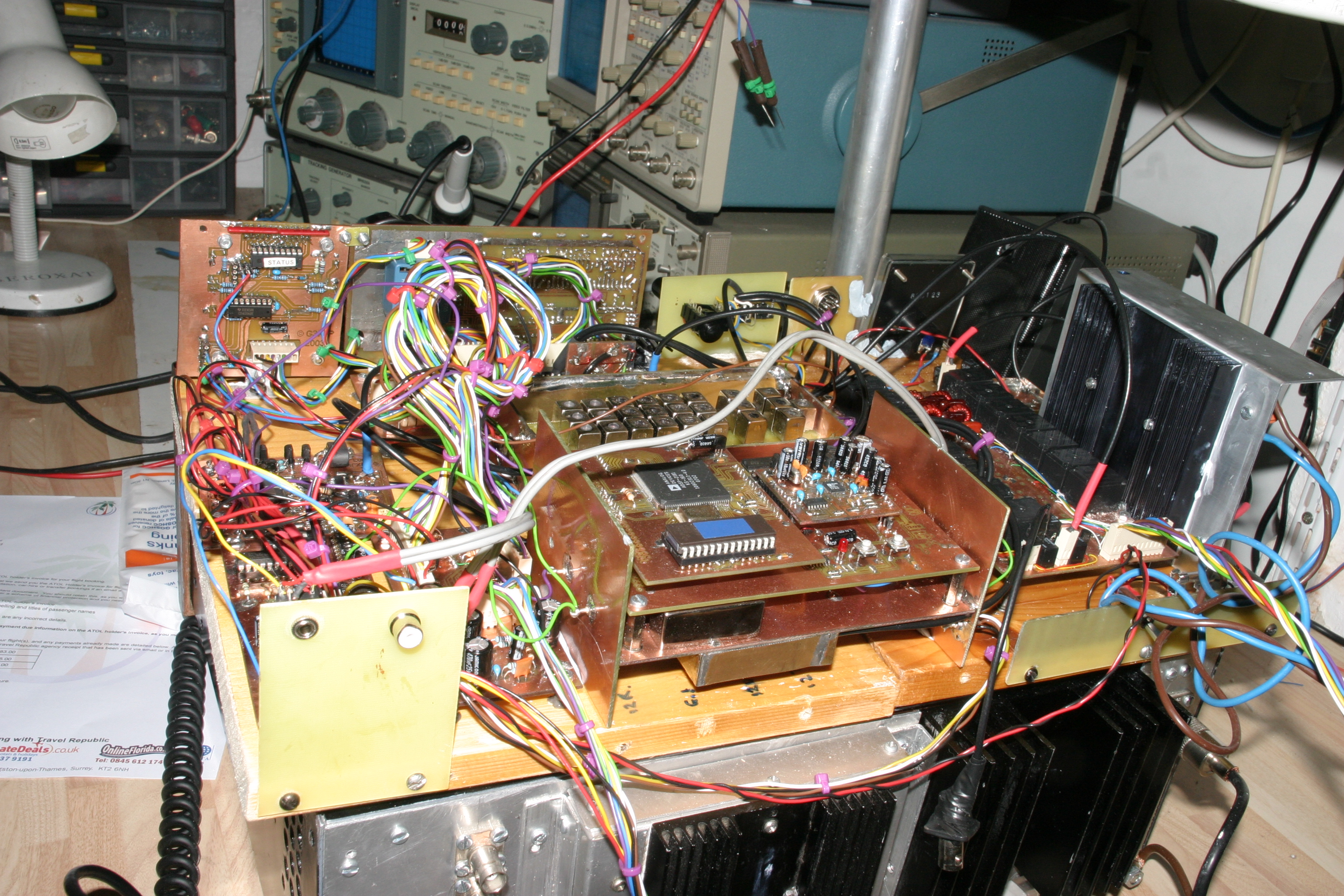
Front View
Built on a piece of old pine shelving - some bits screwed down .. blu-tack for the rest
1/11 Front View

Chris Honey bipolar PA on left
Bought as an old unopened Cirkit kit on eBay April 2007.
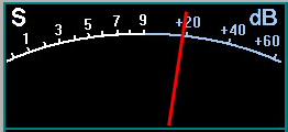
3rd order IMD -30dB at 20watts with 13.2V supply( -23dB at 20watts on 12.6V
supply)
2/11 Chris Honey bipolar PA on left
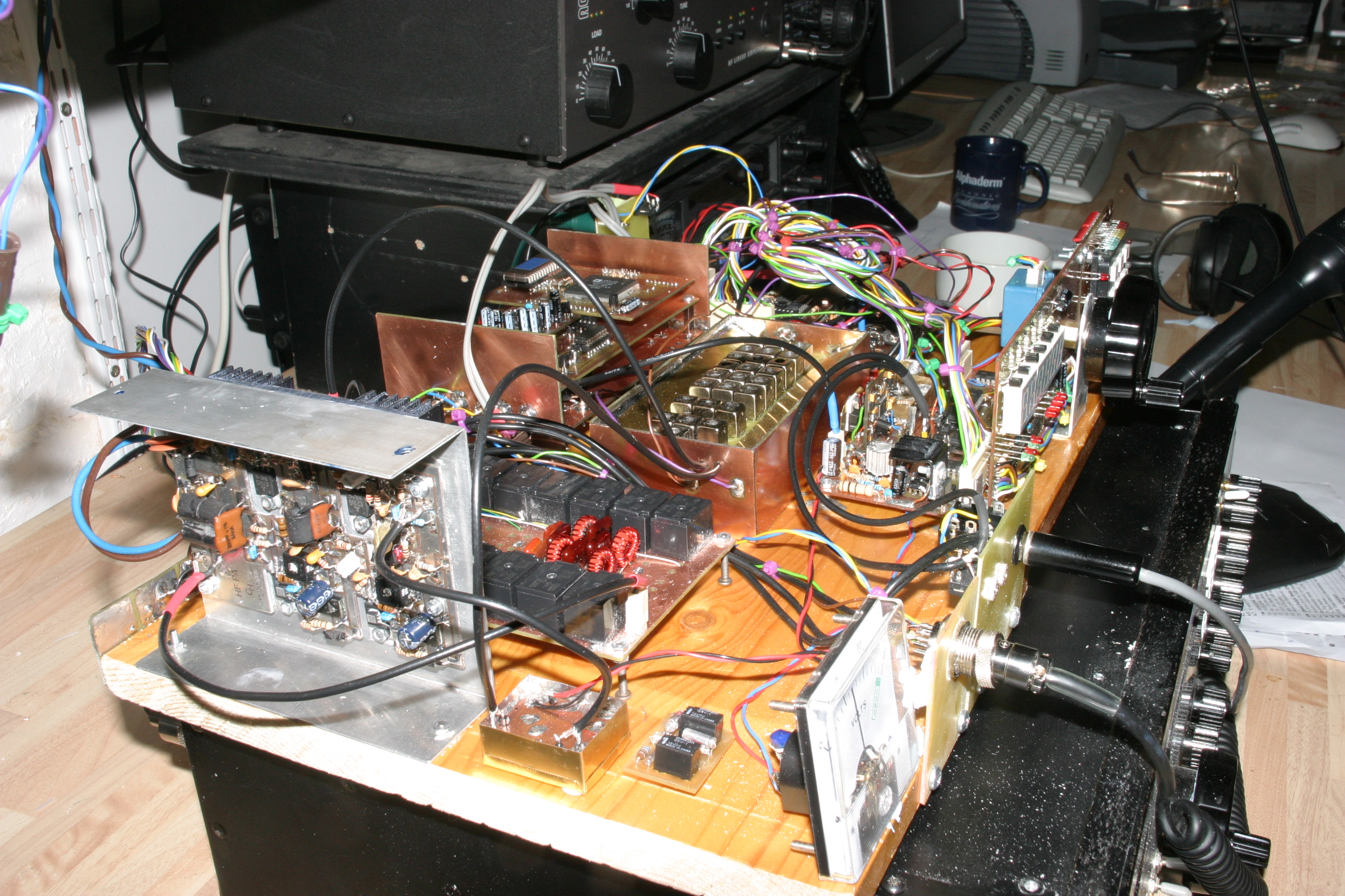
Some big coils of wire
17way cable from
DDS unit to timer unit has PCB connectors on both ends
I will eventually cut this in half and maybe route it out of the DDS compartment via feed through caps
I will eventually cut this in half and maybe route it out of the DDS compartment via feed through caps
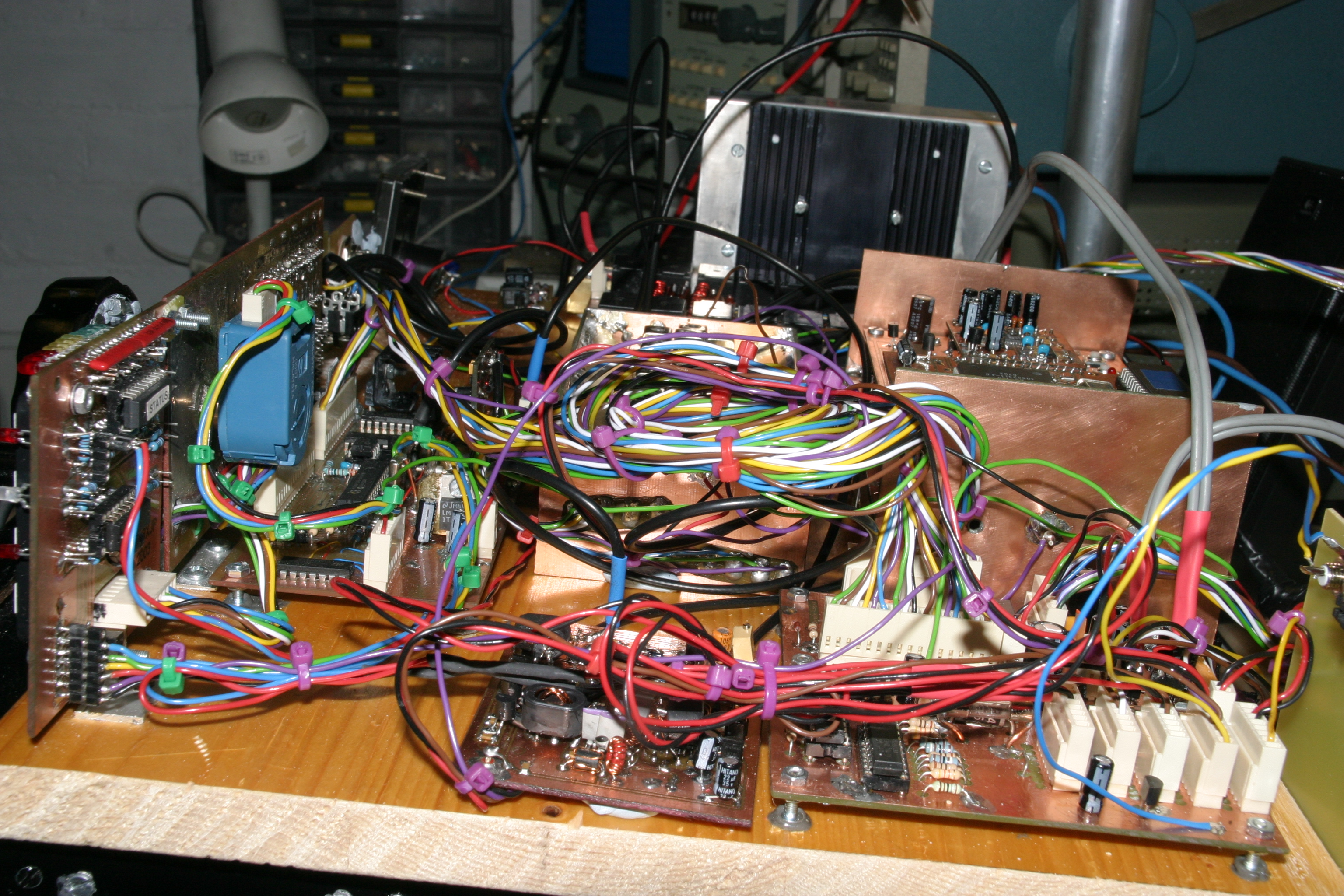
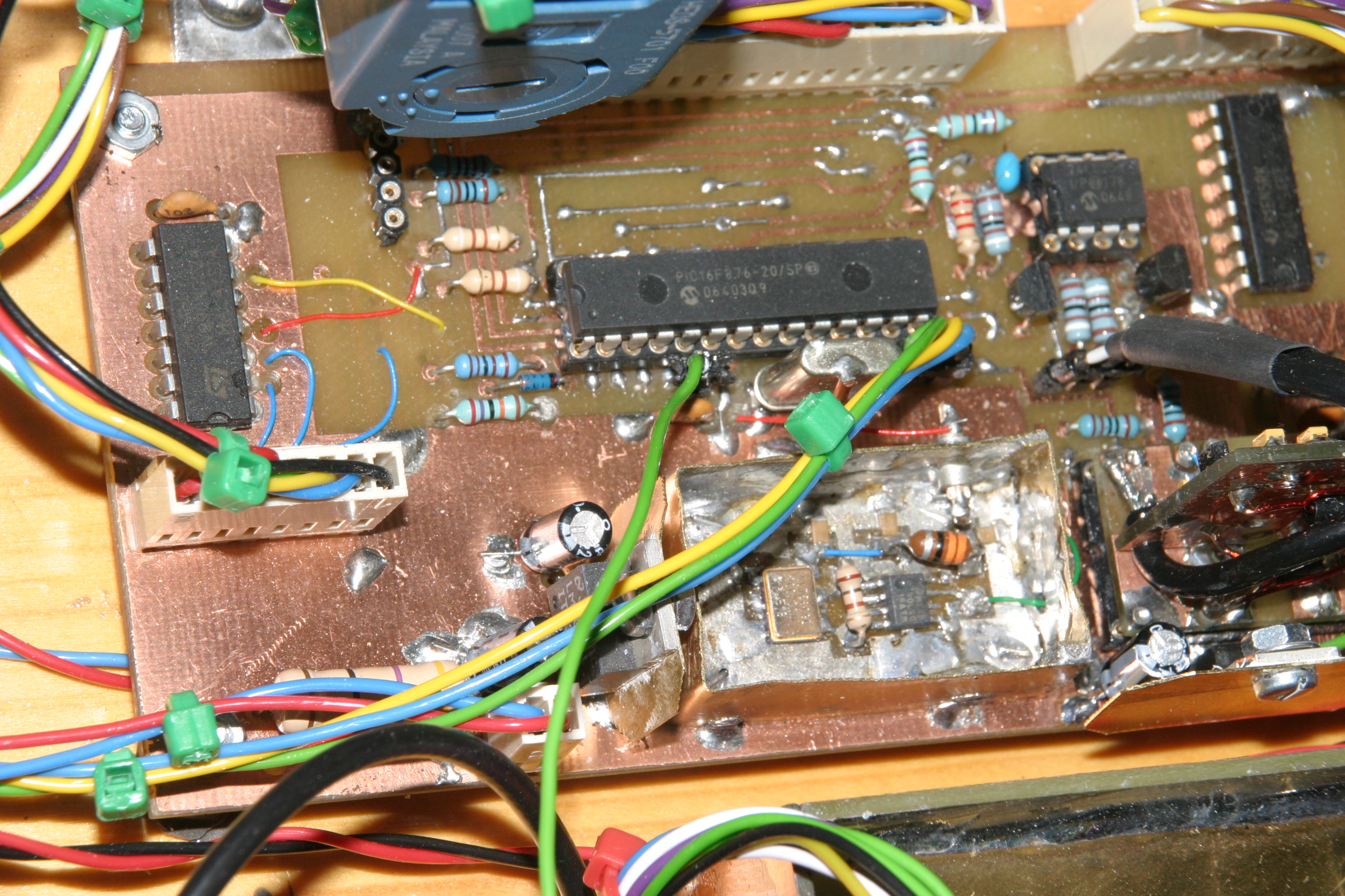
DDS unit
using Agilent rotary encoder
(eBAY!) - interfaced using a 74HC74 - works fine.
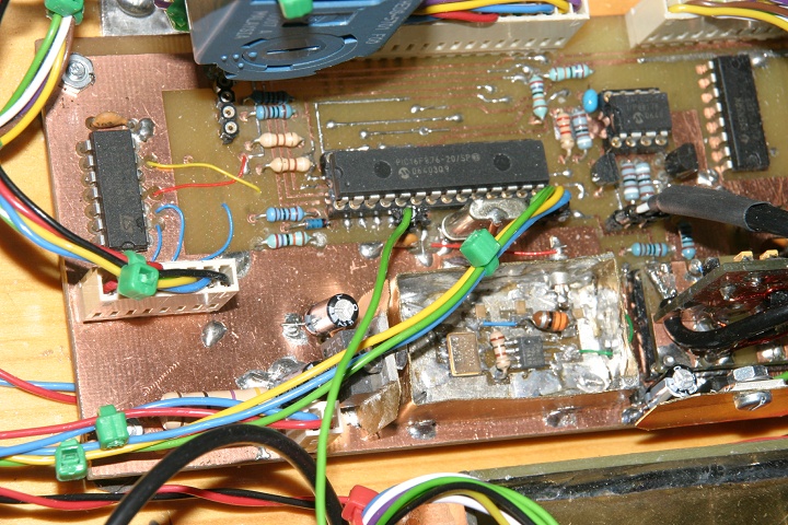
74HC74 on left and cable to rotary encoder
200Mhz oscillator unit at bottom - Pletronics LVDS o/p & LVCS to 3.3v CMOS
logic convertor (=LVDS line receiver)
Regulators with brass shim heatsinking (3.3v for osc and 5v for DDS unit)
Regulators with brass shim heatsinking (3.3v for osc and 5v for DDS unit)
Rear view
Audio out and phono to switch
linear on left

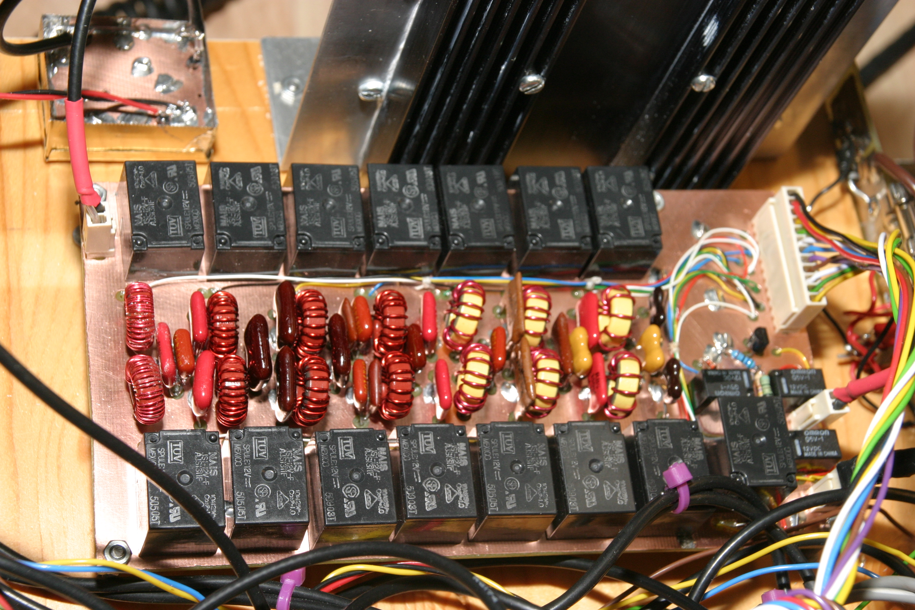
LPF unit
Note seven LPFs - separate for
30m and 40m.
Three small relays: two to switch 20dB attenuator. one to ground Rx input on transmit.
Note use of wire wrap wire for relay control signals.
Three small relays: two to switch 20dB attenuator. one to ground Rx input on transmit.
Note use of wire wrap wire for relay control signals.
L & R
Tx LPFs left, RF
BPFs right


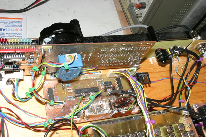
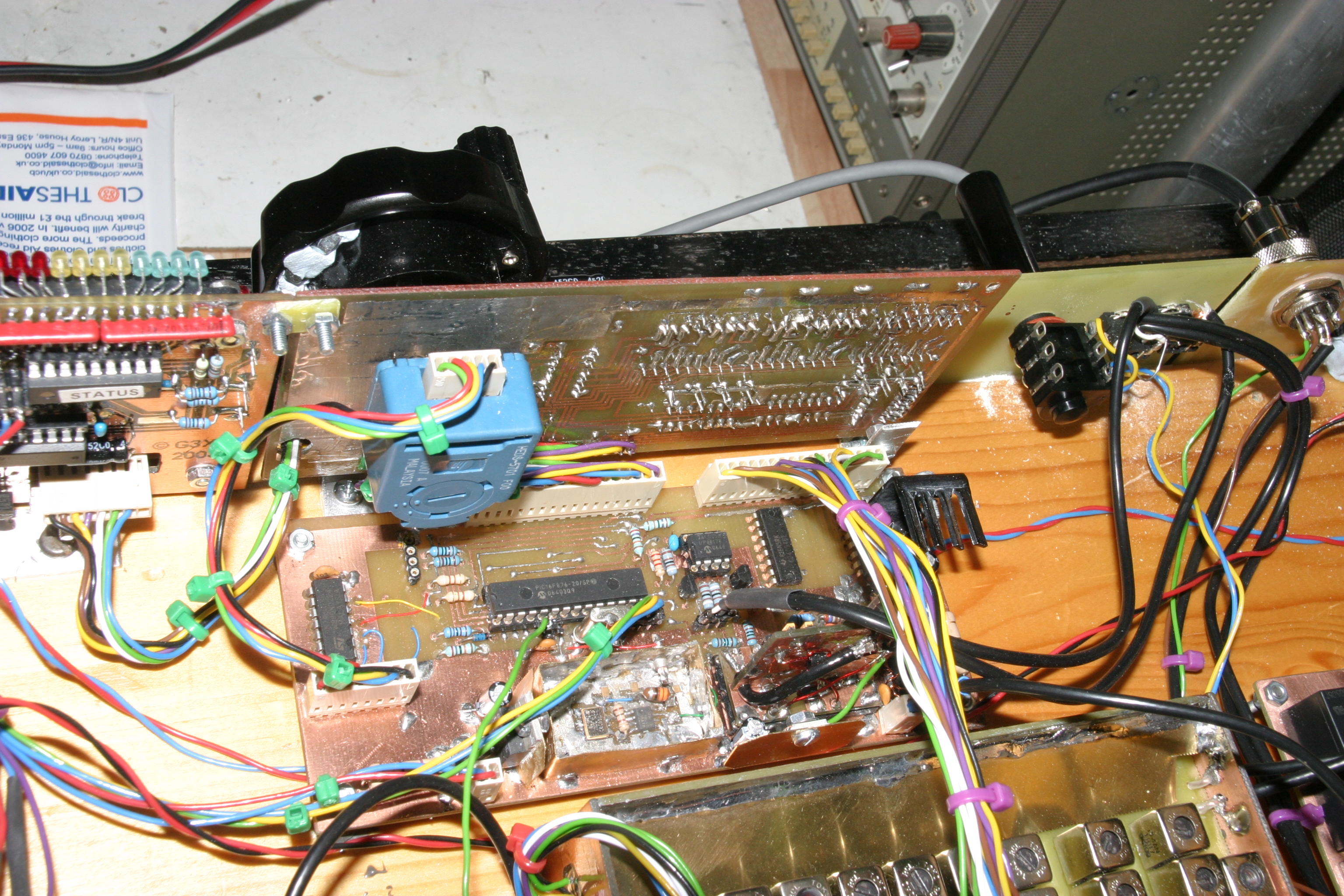
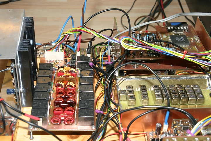
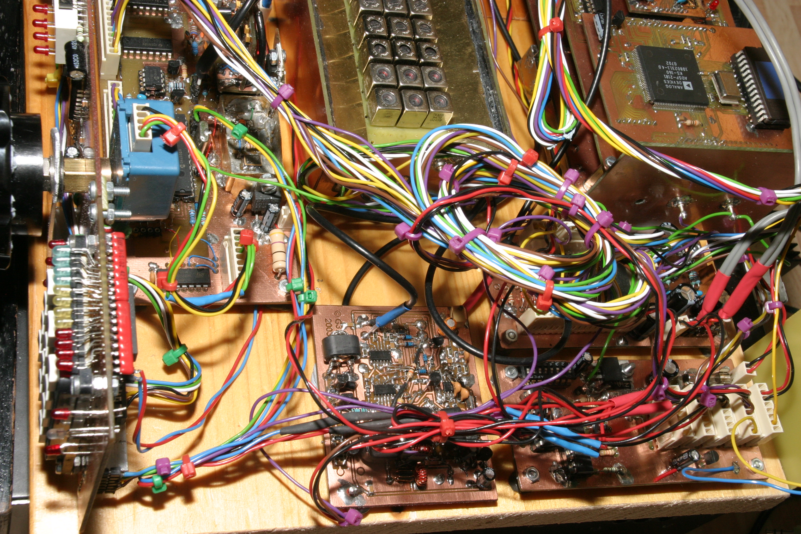
Overview (part)
Magic roundabout bottom centre. Timer board
bottom right. Diode logic and stereo PA beneath coiled wire.
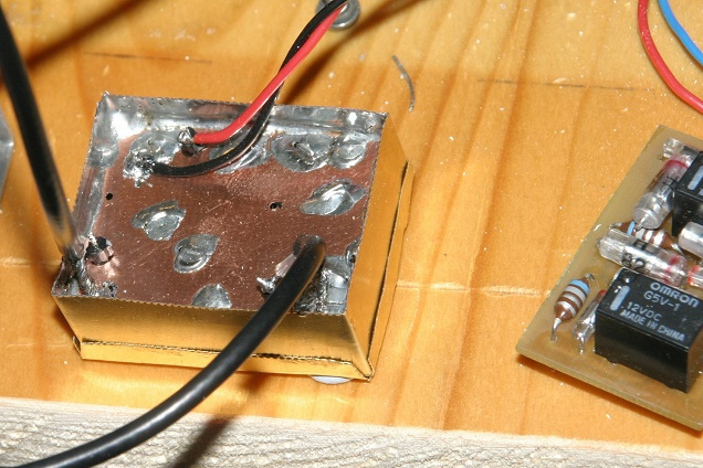
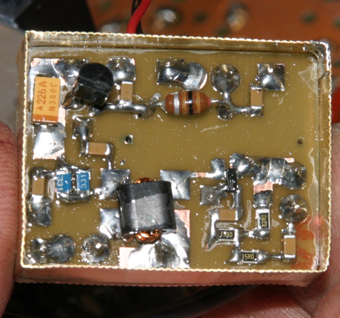
PA Driver Amp
Underside view
18dB gain, so has 5dB input pad. Operated with 8v supply from 78L08 regulator and Id = 37mA. (Initially tried 25mA ... but increasing to 37mA reduced 2nd harmonic from -37dB to -45dB.
18dB gain, so has 5dB input pad. Operated with 8v supply from 78L08 regulator and Id = 37mA. (Initially tried 25mA ... but increasing to 37mA reduced 2nd harmonic from -37dB to -45dB.

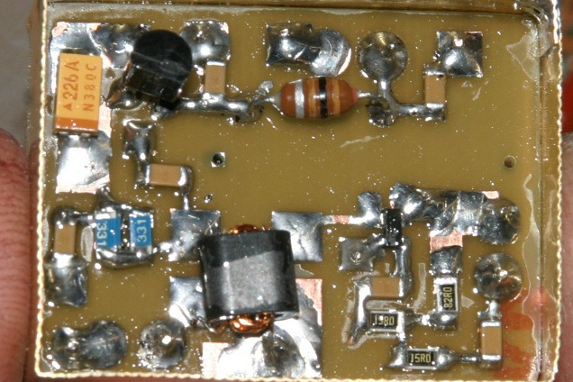
PA Driver amp
Transformer rather than just the suggested choke in the output
- Primary 6t secondary 4t; this halves the current swing as we are
exceeding Idmax on peaks?